Setting up blueprints in Google Sketchup
Loading blueprints for reference in Sketchup is easy. In this tutorial, I'm going to go through two ways of loading an image and arranging it as a background.
Method #1 is best when starting out with a blank document, and when you don't know exactly how big your blueprint object is.
Method #2 is ideal for inserting blueprints into a file with existing geometry.
The techniques do converge though, so I'll be going through Method #1 first, then showing Method #2's different starting points.
Enough with the preamble, here we go!
Method #1
STEP 1: Inserting the Image
Step 1a:
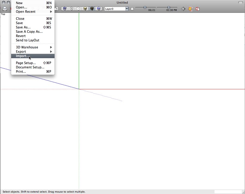
Start with a blank document. Select File:Import.
Step 1b:
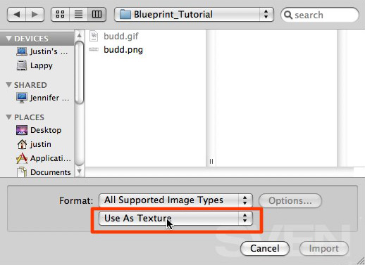
When the dialog box comes up, select Format: All Supported Image Types and Use As Texture (the highlighted box in the image below.
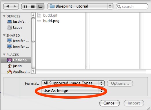
Then select the appropriate image file, .jpg or .png both work well. GIF format, however, will not work in Sketchup, so make sure you convert your blueprints first! (Note that the .gif blueprint file is grayed out.)
Step 1c:
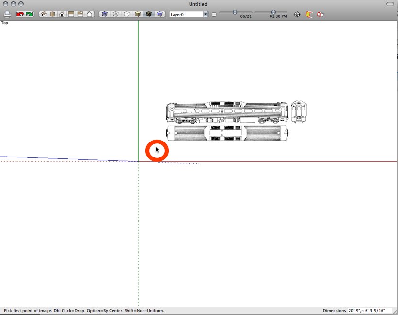
Once the image is selected, you will be able to place it anywhere in 3d space in the document. The image will be glued to the cursor at this point, move the cursor and the image moves with it. The best place in this method is to put it at the origin. Do this by clicking once where you want the image's insert point to be.
Step 1d:
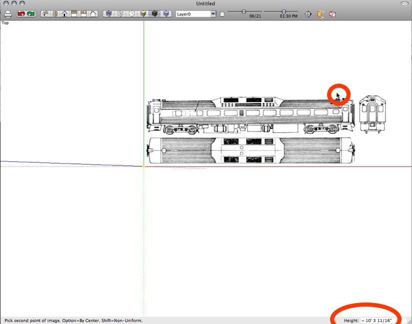
With the image insert point set, the image's lower left corner is pinned to that point, moving the cursor scales the image. This is a clumsy interface, so just make it big enough to fill the screen. The image should be laying in the Red-Green plane, or in other words, laying flat on the ground. Note the Value Control Box (VCB) in the lower right corner, it lists a size, but it doesn't really mean anything at this point. Set the size by clicking again when the image looks about right. The image will stay proportional through this process.
 STEP 2: Scaling the Image
Step 2a:
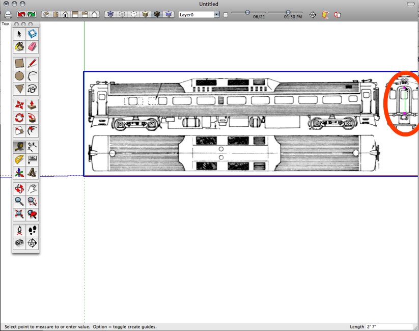
With the image inserted, now it's time to set the scale more accurately. Select the Tape Measure tool, either from the tool palette, or the hotkey is "t". Find a known reference point in the drawing, in this example I'm using the door. Click once to set the initial measure point at the bottom of the door and a second time at the top of the door. Note the value in the VCB.
Step 2b:
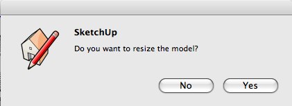
Before clicking again, and that is an important point, type in the known dimension, in this case 6' 8". You don't have to click in the VCB to activate it, just start typing. Once the value is entered, click enter. This sets the value. A warning box should pop up asking if yo want to resize the drawing, select yes or ok.
Now the image is scaled correctly. This is a good trick and you can resize components or groups this way too by activating it and using the tape measure tool inside the active group or component in just the same way. The desired value may have to be re-entered. It might be a bug but it doesn't happen all the time.
You can stop here if you want. The image is in the model at a real size and can be traced over. The image is not a Sketchup texture yet, but an inserted background image so to speak. It's still an object and can be moved, scaled and rotated in any direction. It will show up in all of the rendering styles, including wireframe. In actuality it is really just a special kind of group at this point. Leaving it like this is especially useful for floorplans, maps, or site layouts. But for something like this train we need to take it further, and turn the image into a texture.
STEP 3: Converting the Image to a Texture
Step 3a:
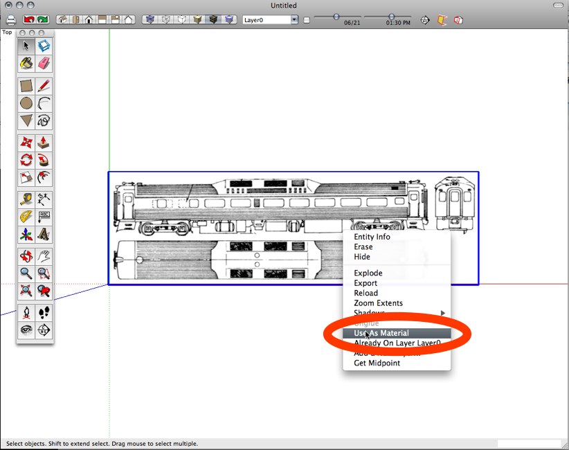
Right click (control-click on a Mac) and select "Use as Material" from the context menu. This will add it to you material palette. The image object now will only display in Textured Shaded rendering mode.
Step 3b:
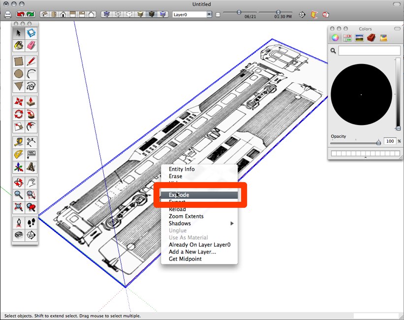
The image is still part of a group. That means it is isolated from other geometry in the model. I want to use it though to draw on, so I need to explode the group. Right-click again on the image and select "Explode" from the context menu. I've orbited a bit to see the results a bit better.
 STEP 4: Draw the Reference Geometry
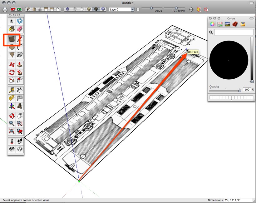
Step 4a:
Use the Rectangle tool ("R" hotkey) and draw a rectangle roughly the size of the top view. I can be a bit imprecise here as I will tighten it up as I go along with the other views.
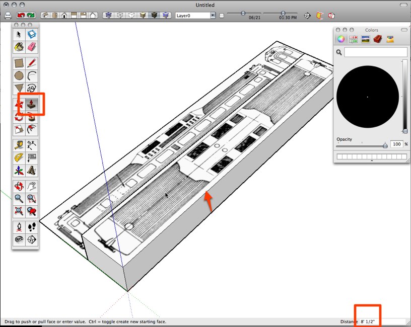
Step 4b:
With the rectangle set, it creates a face on the image plane (which became a basic face when it was exploded). Now, take the Push/Pull tool ("p") and "pull" this face up, again the exact distance doesn't matter, just estimate the height of the object.
 STEP 5: Positioning the Textures
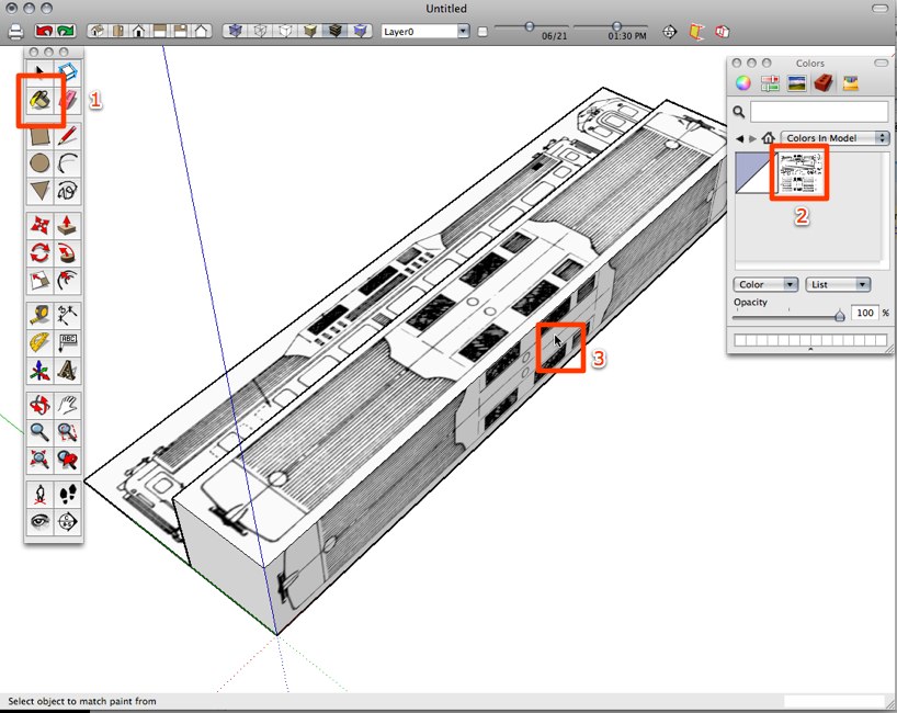
Step 5a:
With the box extruded by the push/pull tool, it's time to start positioning the textures on each face. Start by selecting the Paint Bucket tool ("b") number "1" in the image below. This will by default also activate the materials palette. Select the texture from the materials palette (number 2 in the image). It can be found by clicking on the Home icon or from the pull-down under "Colors In Model". As an alternative I ofter use the Eye-Dropper tool. This samples the texture from the model by Alt+clicking (Command+clicking) making sure the Paint Bucket is the active tool. This changes the cursor to an Eye-Dropper. Alt-click on the texture and it loads that as current, release Alt and it turns back to the Paint Bucket. With the Paint Bucket, click on the side face (number 3 in the image).
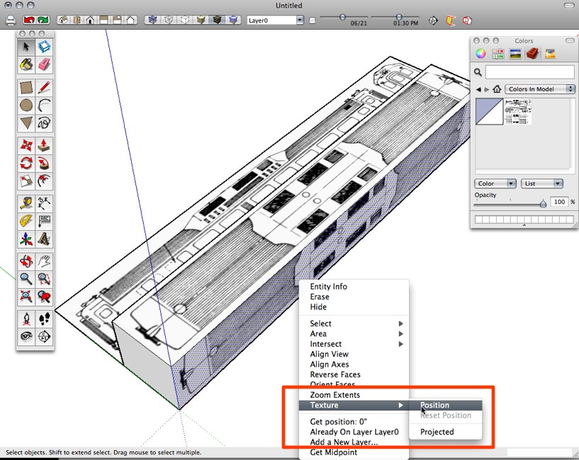
Step 5b:
The texture will be positioned incorrectly at this point, but it's real easy to fix. Right click on the side face and select Texture:Position from the context menu.
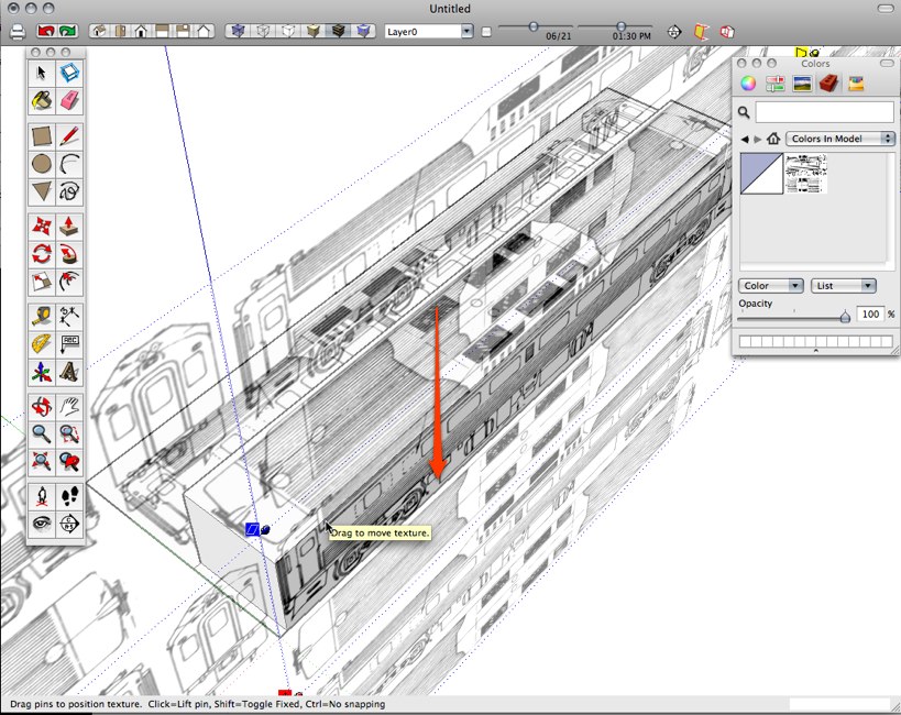
Step 5c:
This will bring up the texture editing interface, which basically displays a tiled image of the texture. By default it is in "Fixed Pins" mode, and this is what we want. Position the image so the correct part of the texture is aligned with the reference geometry. Remember though, that at this point my reference geometry is still rough. When the position is correct, right-click and select done or hit enter or space to exit the texture editing interface.
Step 5d:
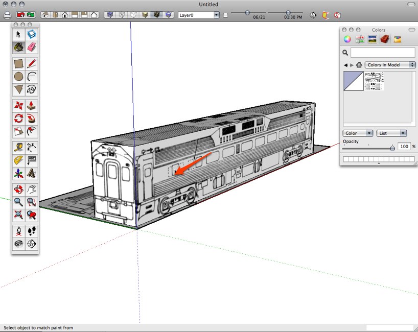
Repeat 5a and 5b on the remaining sides. I use the Eye-Dropper on the side face (with arrow) to select the texture than paint it on the front face, positioning it correctly.
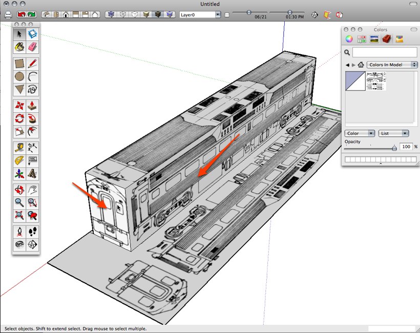
For parallel sides, use the Eye-Dropper to select the opposite side, this may save some moving. But the texture may need to be "flipped". Flip and image by entering the texture editing interface and right clicking and select Flip Image and then the direction of the flip. The two faces with arrows were flipped in this manner.
 STEP 6: Cleaning up the Geometry
Step 6a:
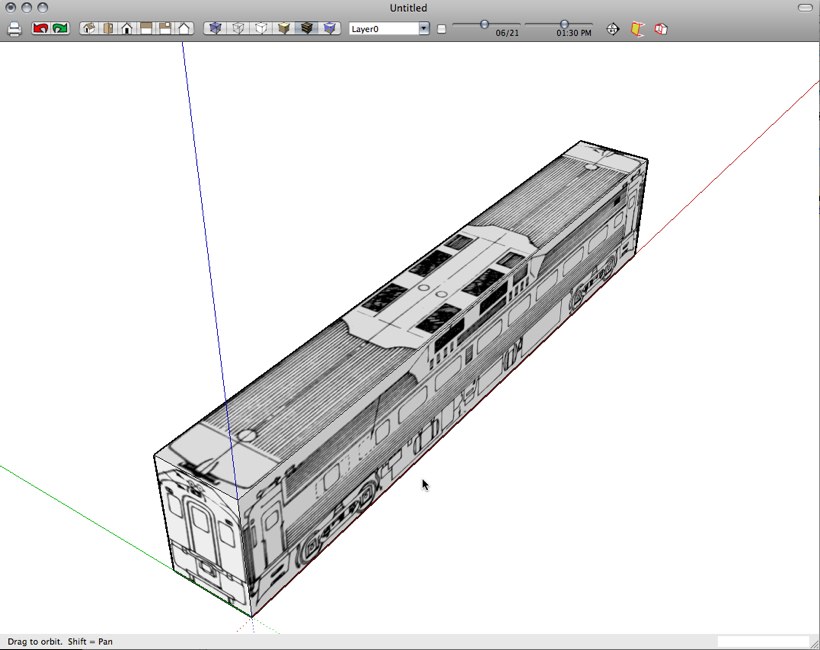
Using the Push/Pull tool, move the faces so they line up correctly with the reference image on the texture.
Step 6b:
Erase the unwanted flat texture, leaving only the box. This leaves an accurate base for further modeling! The faces can be split apart and moved around depending on the modeling technique for the rest of the model.
Method #2:
Use this method with existing geometry approximately the right size.
 STEP 1: Inserting the Texture
Step 1a:
With a rough box already drawn, select File:Import. This will bring up a dialog box. Select "Use as Texture from the pulldown. Then select the image.
Step 1b:
The texture comes in pinned to the cursor. Place it on the corner (highlighted with a circle in the image) by clicking once. After the first click, the image will scale along with the cursor movement. Scale the image up so it fills the top of the box, then click to set its size.
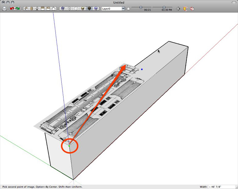
This will result in the image clipped to the top face of the box.
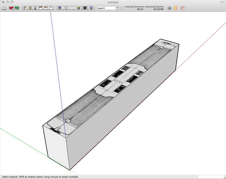
From here, just repeat Steps 5-6 from Method #1.
Thanks for reading this tutorial. There are some very important and powerful Sketchup tools introduced here. Play around with the texture editor, it can do a lot of interesting things. Happy modeling!


