Setting up blueprints in Softimage
Here's just a simple tutorial on setting up your blueprints in Softimage|XSI version 5.0. I will cover two techniques, one is called Rotoscopy and the other is called image planes. Setting up image planes basically means setting up grids with textures, while rotoscopy is more like putting a backdrop image onto your camera.
I'll use a Ducati motorcycle to demonstrate. First I just want you to know that the blueprints are divided into Front.jpg, Side.jpg and Top.jpg by using a image editing software like Photoshop. And I have while in Photoshop ensured that the images are infact lined up. This is very practical because then I dont need to tweak anything while in XSI.
Rotoscopes
step 1. When setting up rotoscopes you simply open the "Rotoscopy Options" Property page for any of the views, see fig 1. This Property page (or PPG as I will call it from now on) has all the options for tweaking your rotoscope.
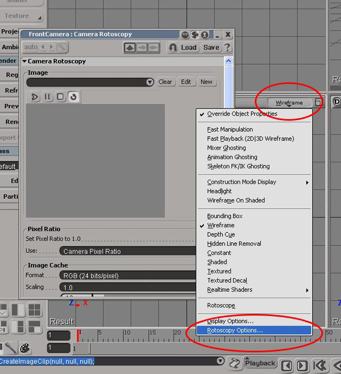
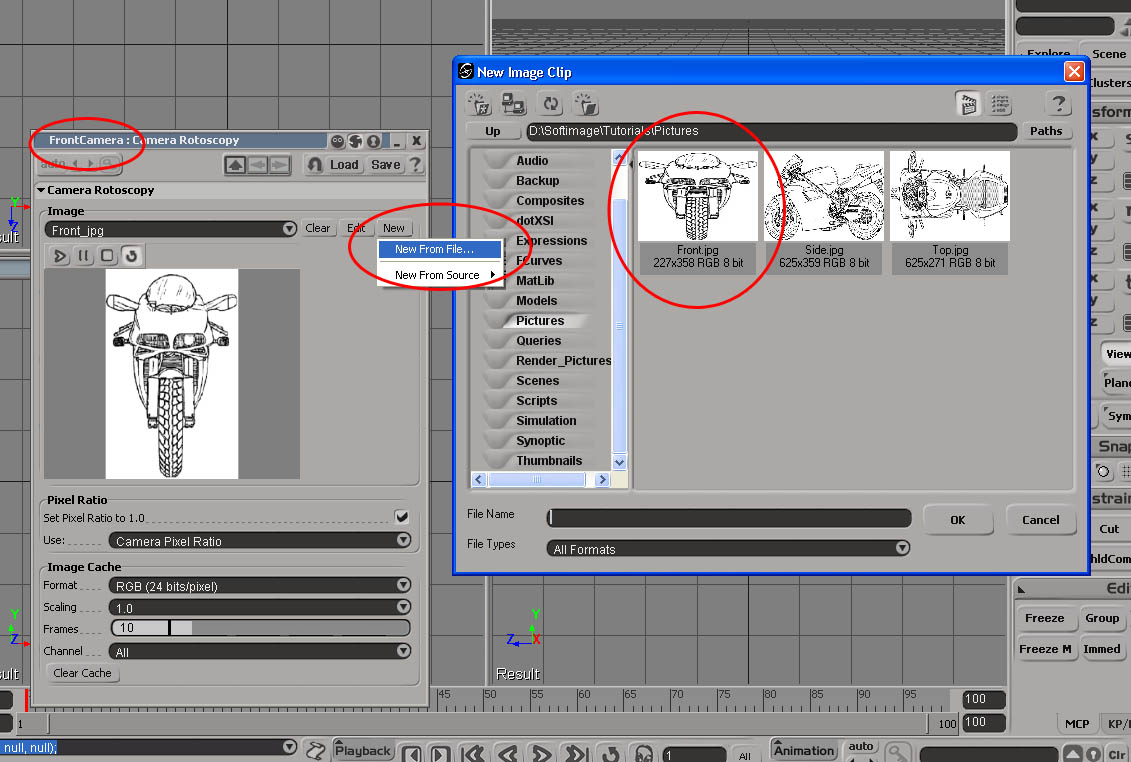
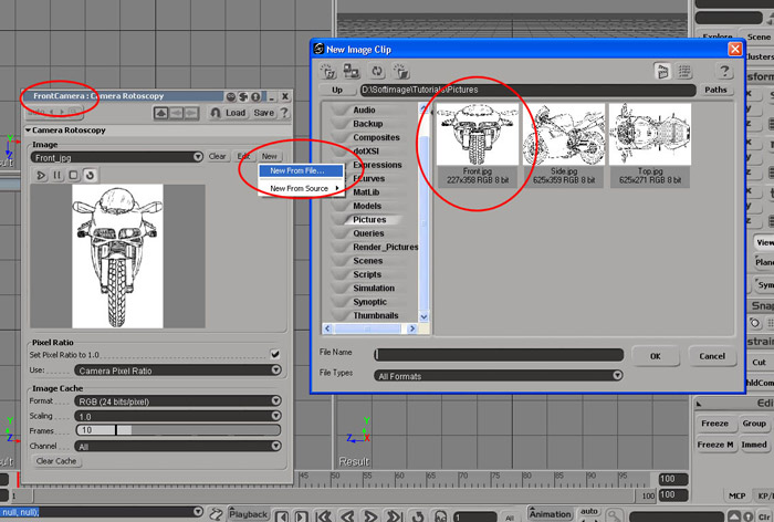
step 2. Then click the "New" button and "New from file". You are then taken automatically to the "Pictures" folder of your current Project, this is where I suggest you place all your reference images and textures (see fig 2). Choose the correct image for your current camera. If you are in doubt which camera you are setting rotoscopy for then take a look in the top left corner of the "Rotoscopy Options" PPG.
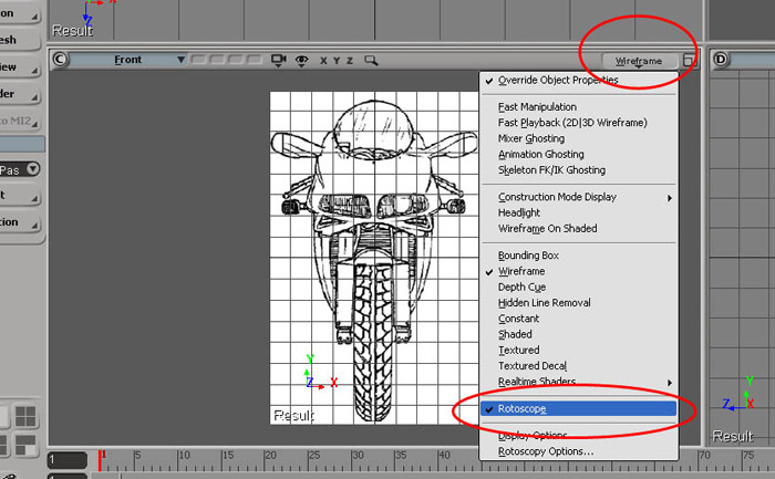
step 3. Now to view your rotoscope in viewport you need to click on the "Rotoscope" button for that given viewport, see fig 3. This button works as a toggle. You will notice that the image apears and that there is a dark gray color around it.
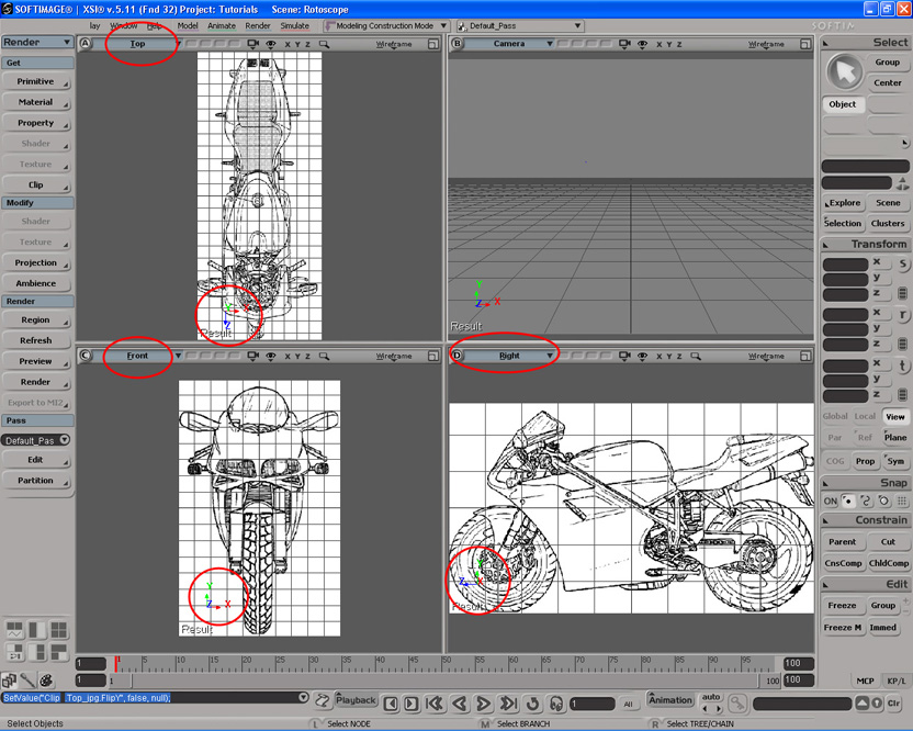
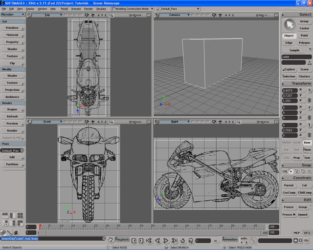
step 4. Now I suggest that you follow step 1-3 in the other viewports so that the Front, Side and Top views all have rotoscopes. Be sure that all the views have the correct images attached to them, and be sure that the images are rotated correctly. You can check that the manipulator in the bottom left of each viewport lines up and makes sense. For eksample in my case I had to rotate the top view Rotoscope downwards so that the z-axis defined the lenght of my Ducati, see fig 4.

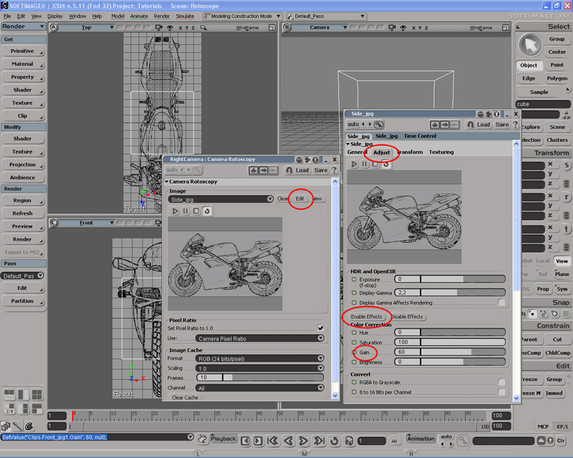
step 5. Next I darkened the Rotoscopes by going to the "Rotoscopy Options" for each of the viewports and clicking on the "Edit" button in the PPG (between "Clear" and "New"). Then I went to the "Adjust" tab and down to the "Gain" slider and set that to about 60. You need to push the "Enable Effects" button before you can adjust those sliders, see fig 5. Now it's much easier to see geometry in the background.

step 5. Now it's time to match the viewports to eachother. The thing to know is that the images move along when you use any of the standard navigation keys. So what you can do is simply to use the grid as reference and line the images up by pressing the "S" key. It'very practical to use the "shift" together with the "S" key to constrain the navigation to one axis only.
The method that I like to use is to put in a box with the bounding volume of the thing I model and match the rotoscopes to it, see fig 6. This might take a little bit of time to get right.
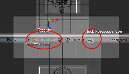
step 6. Lock the Rotoscope by clicking on the icon in fig 7. This will make sure that the Rotoscope stays put so you can navigate properly whitout it following. Thats it! I also recommend to store a memory cam by middle clicking on one of the four available slots. That enables you to come back to that exact stored view everytime you left click on one of the stored memory cams.
One last thing to know is that you should not use the "A" or "F" keys because this will unlock the rotoscope and frame the view to the model.
That should be everything you need to know about rotoscopy in Softimage|XSI when modeling.
Image Planes
The alternative to rotoscopes is to set up images planes, this is my prefered method.
step 1
First you need to find out the resolution of the images, there's many ways of doing that but I usually do it in Photoshop. And when in Photoshop I also make sure that the main features of the blueprint match up, this is good practice.
My images are: Side.jpg - 625 x 359 pixels, Top.jpg - 271 x 625 pixels, Front.jpg - 227 x 358 pixels
Step 2
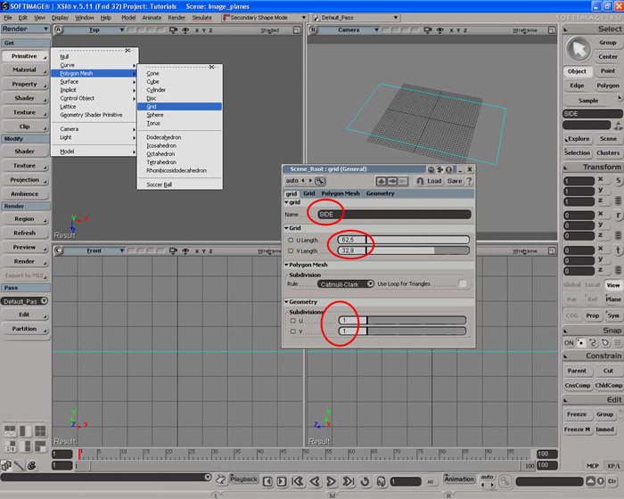
Then you need to get a grid "Get/Primitive/Polygon Mesh/grid" name it "SIDE" and set the Subdivisions to 1 in U and V, then enter in the resolution in "U Length" and "V Length", for example in my case I enter in 62,5 in U and 35,9 for my Side image plane, see fig 8.
After that I go and get another grid, name it "TOP", set the subdivisions to 1 in u and v and set the U length to 27,1 and V to 62,5. And then again the exact same thing for the Front, exept the U and V Lengths are in my case 22,7 and 35,8.
Step 3
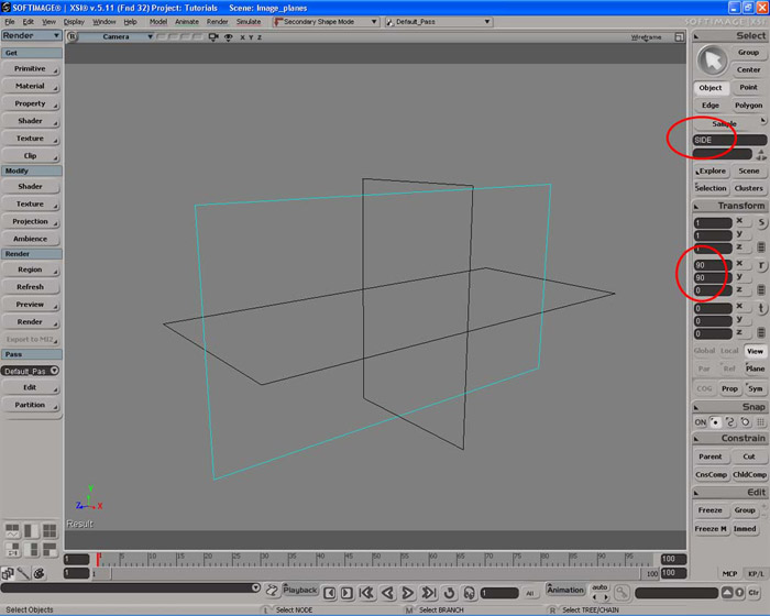
Now we need to Rotate the right grids to face the right axis, this is very easy, see fig 9. In my case I had to rotate the "SIDE" grid 90 degrees in X and Y, "FRONT" grid to 90 in X and the "TOP" grid was just fine the way it was. A tip is to hold "shift" while you rotate to snap to 15 degrees increments.
Step 4
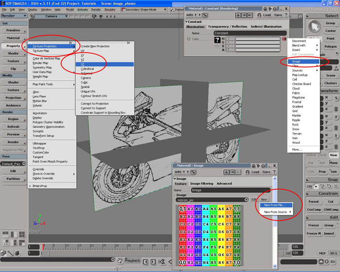
Now we need to apply a texture projection to each of the image planes. In my case I'll start with the side view so I select the "SIDE" grid and go to "Get/Property/Texture Projection/XZ". Then apply a new material "Get/Material/Constant" and in the property page that pops up click on the little icon next to the Color (on the right) and go to "Image". A new ppg pops up, click "New/New from file" and select your Side blueprint, see fig 10. Then apply this exact same workflow to the Top and Front grids. Turn on the display type to "Textured" to confirm that the image is correct.
Step 5
Freeze all of the objects by selecting them and clicking the "Freeze" button in the lower right of the interface under Edit.
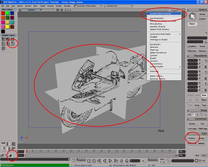
Now you just need to click the little palett icon in the bottom left of the XSI interface and click on "T" under Display types and Pick all three Grids. Then go in every viewport under the Display meny and check Off the "Override objects properties", see fig 11.
Step 6
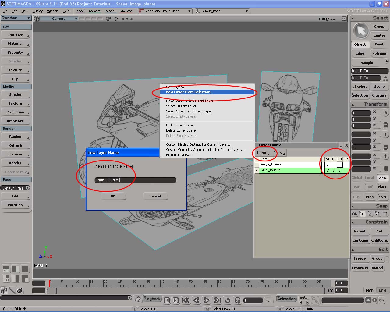
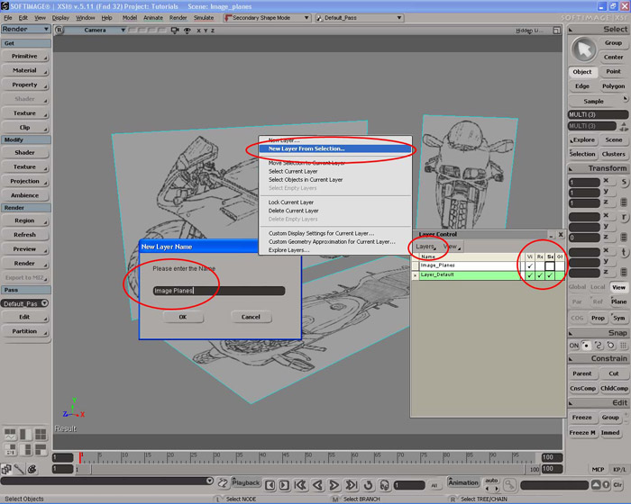
Select all three grids, tap 6 on your keyboard and in the Layers ppg go to "Layers/New Layer from selection" and call it "Image planes". Then check of "Select" and "Render next to the newly created layer, see fig 12. You'll also notice that I have scaled the images down, just select all three image planes, hit "X" for scale and also turn on "COG" under the Transform menu. I also added a little bit of transparency to the materials, just make sure that "Transparency enable" is checked on under "Display options".
Thats it!
Thanks
Kjartan Tysdal