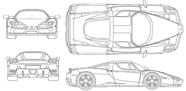
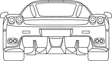
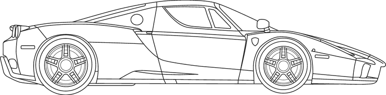
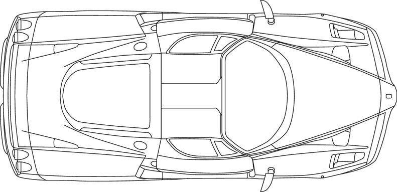
Well pretty essential in this tutorial is naturally having actual blueprints... I picked the one that I just (re-)made an hour
ago, the ones for a Ferrari Enzo.
Now crop all the different views in PhotoShop so that they fit exactly in the image (see below). I have made a small error with the mirrors (the Enzo has two differently sized ones, but I used one for the front and one for the rear, and naturally picked the two different ones...:), so the front and rear are not exactly as wide. Doesn't really matter, just that you know.
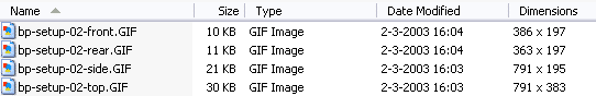
Alright: now save these images (or the ones from your blueprints) with some easy names, like bp-front.jpg, bp-side.jpg etc.
This will come in handy when we have to pick them later on, bp-01.jpg doesn't really say much...
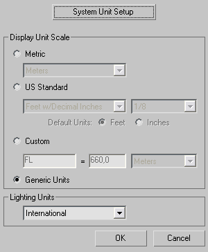
But before we go on do this: in the customize menu select 'Units Setup':
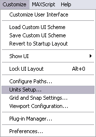
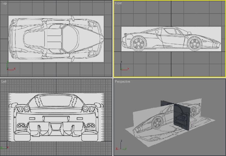
And set it to 'Generic Units', meters don't really mean much when your 3D'ing, it's all about relative sizes, not absolute, as seen below.
Now in explorer (or with something like ACDsee) try to find out what resolution all the different parts have, if the blueprints are good then the top would have to be as wide as the side, and the front and rear should be as high as the side and finally the front and rear should be as wide as each other. In this case you can see (image below), that the front and rear are not as wide, this is because of the mirror-issue. But the rest matches up very nicely, if I may say so.
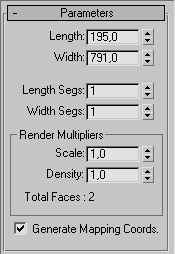
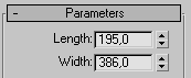
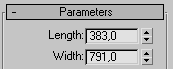
Now create a plane with the size of the resolution that the side image has, so in this case 791x195, set the length and width segments to 1.
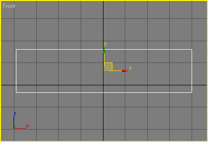
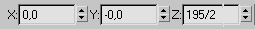
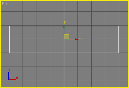
Fill in the following values in the absolute position at the bottom of the UI (User Interface). I used 195/2, because the pivot point is at the middle of the plane, so the z position of the plane is half as high as the height of the plane: 195 / 2.
Et voila: the plane is positioned perfectly:
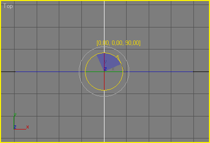
Now clone this plane (Edit > Clone) and rotate it 90 degrees.
Change the size of the plane to match the front view:
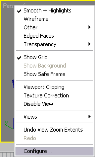
Before we continue we first set some viewport options right, so that it won't cause problems later on. For instance when you work with planes and don't put 2-sided on, it doesn't show in certain viewports, very frustrating. So right click on 'Perspective' and click 'Configure...'.
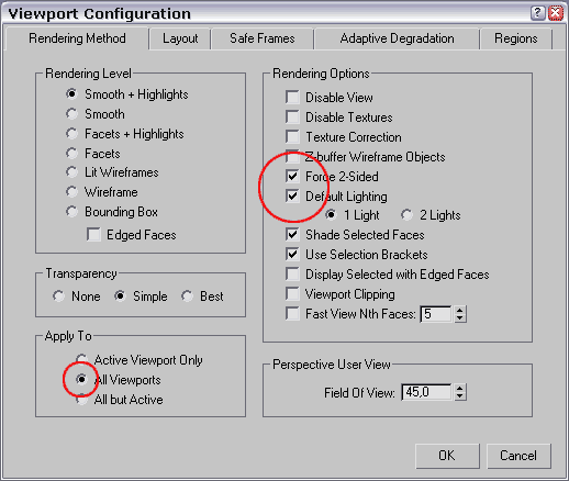
Click the '2-sided' and 'Default lighting' radio buttons and set 'Apply to' to 'All viewports'.
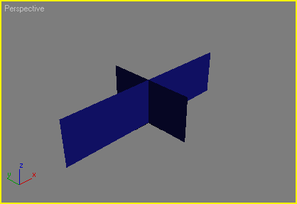
Now your perspective view should look something like this (if not then it might be that you have to press 'F3', this toggles between Wire-frame and Smooth and Highlights mode.
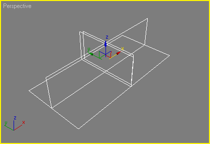
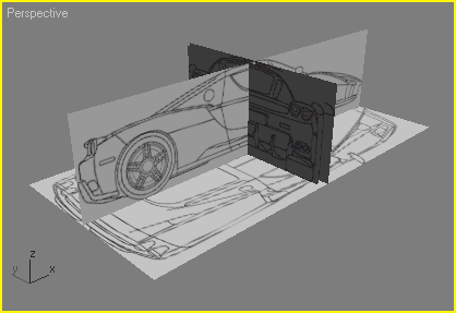
Create the remaining two planes yourself, with the right sizes (= matching their image view sizes) and positions. At the end of that you have something like this (I don't put the front and rear at the same x-position since they would interfere with each other):
Rename all your planes to something so that you can find them easily, stuff like BP: Front always works easily, I tend to just name them after the view they represent, so Front, Rear, Side, Top.
That was the setup of the planes, now we are going to apply the right materials to the right planes. So open the Material Editor and in the first slot click the small square for the diffuse material...
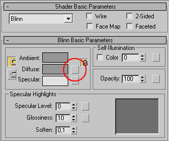
...from the pop-up click 'Bitmap'...
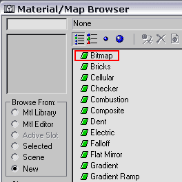
...and select the side view from the blueprint, in my case bp-setup-02-side (from this tutorial):
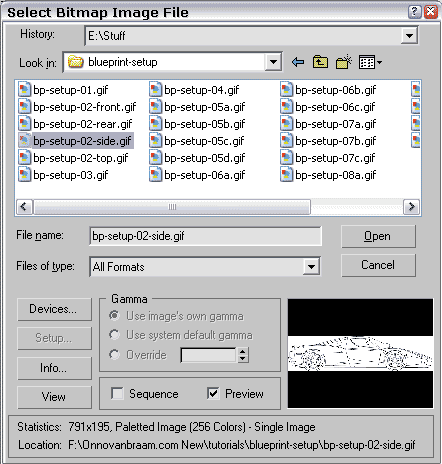
Select the plane called 'Side' and apply the material, also click the checkered square to 'Show map in Viewport':

Repeat this step for all planes and all their corresponding bitmaps.
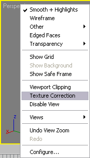
Now right-click perspective again and select 'Texture Correction', this makes sure they are shown rightly in the viewport, sometimes they don't really do what they're supposed to, the texture correction solves this.
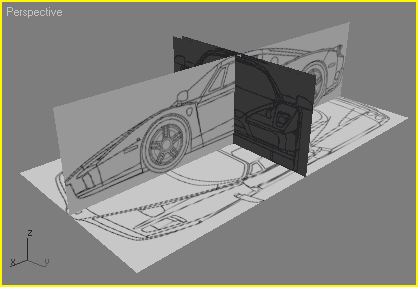
What you should have is this (almost finished now! :):
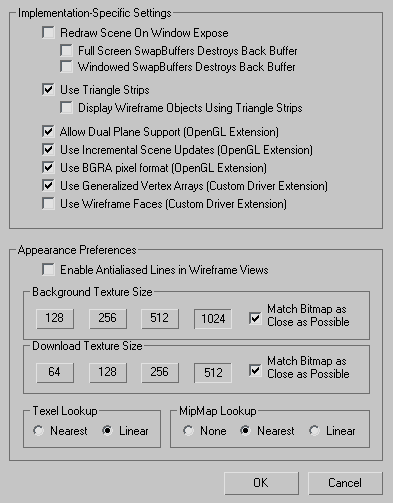
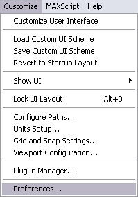
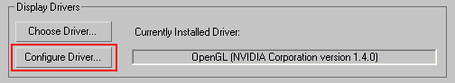
The final step is to change the setting to optimize the quality of the texture in your viewports, so go to Customize > Preferences... > Viewports > Configure Driver
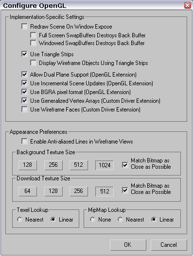
The only things you should change are the 'Apperance Preferences'. I have them like this, this may differ for other video cards (I have a NVidia GeForce 4 Ti4200 64Mb...).
That's it, we're done. You may want to rotate the planes if they don't match with your viewport names (as I have here, the side is in the Front viewports), but that doesn't really change much, they're all orthogonal...